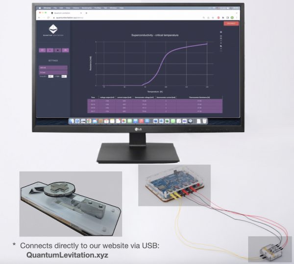
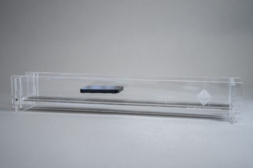
Superconductivity introduces one of the most technically difficult challenges for physicists – designing a measurement setup that is sensitive to very low (and zero) voltages and resistances and to high voltages and resistances at the same time. Below we give a short review of how physicists – and students – can measure superconductivity in the lab using readily available equipment.

Resistance, voltage and Ohm’s law
When current passes through a material, the potential energy of the electrons changes along the current path. Voltage is the potential energy (per unit charge) of the conductive electrons, and it is the voltage difference that we actually measure in most experiments. The electrical resistance of any material can be derived from Ohm’s law:
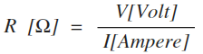
R – the resistance to electrical current, in ohms
I – the electric current, in amperes
V – the voltage, in volts
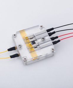 Kit for this project4-point Tc setupFrom $587.00Ships in 1–3 daysView the kit →
The voltage changes as the current flows through any material. However, when the changes we are after are small, we need to filter out voltage drops from unwanted sources such as the contacts, the wires and electrical noise. To solve this problem physicists came up with a clever measurement setup that is sensitive only to the voltage inside the material under question.
2-wire vs. 4-wire measurement
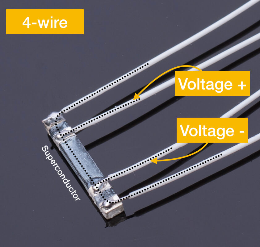
In a 2-wire measurement we inject the current and measure the voltage using the same leads. We measure the voltage outside the superconductor and are therefore sensitive to changes across the contacts & wires as well as to the voltage drop inside the superconductor (if it exists). Since the voltage drop in the superconducting state is zero (and infinitesimally small close to the transition), we mainly sense the contacts & wires.
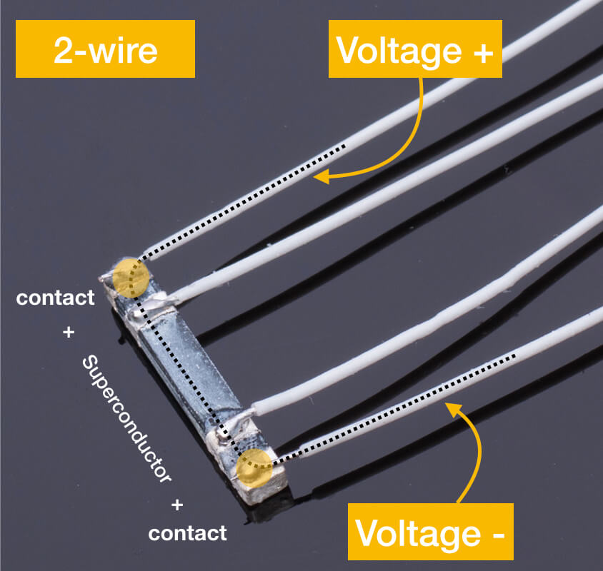
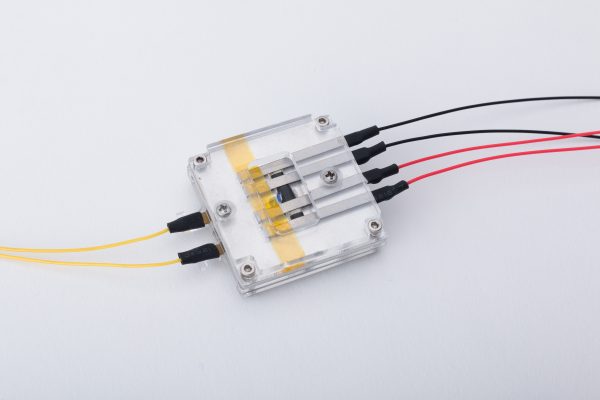
In a 4-wire measurement the voltage probes are connected inside the current path. Current does not flow through the voltage leads & contacts, and hence the measured voltage is sensitive only to the voltage drop inside the material.
Why the 4-wire method matters: the numbers
Once you put numbers on it, the 4-wire (or Kelvin) method stops looking like a refinement and starts looking like a necessity. A silver-painted or clamped contact on a ceramic superconductor typically has a resistance somewhere between a few tens of milliohms and several ohms. The quantity you are trying to see – the resistance of the sample itself – is often in the milliohm range just above the transition and, below it, indistinguishable from zero.
In a 2-wire measurement those two numbers add together, so the contacts dominate the reading. When the sample goes superconducting, the meter does not fall to zero; it falls by an amount too small to notice and settles on the resistance of your leads and contacts. In a 4-wire measurement the voltmeter draws essentially no current, so almost no voltage develops across the voltage contacts, and the reading collapses to the noise floor of the instrument the moment the sample becomes superconducting. That collapse is the measurement.
What the resistance-vs-temperature curve should look like
A superconducting transition measured properly has a characteristic shape, and it is worth knowing what you are looking for before you cool anything down.
- Above the transition the sample behaves like a normal, if rather poor, metal: the resistance falls roughly linearly as the temperature falls.
- At the critical temperature the resistance drops abruptly. For YBCO – the yttrium-barium-copper-oxide ceramic used in most classroom and demonstration kits – this happens at roughly 90–93 K, comfortably above the 77 K boiling point of liquid nitrogen.
- Below the transition the measured resistance is zero to within the resolution of your instrument. Strictly speaking, no experiment ever proves that the resistance is zero; it places an upper bound on it. Onnes could only say that the resistance of mercury had fallen below what he was able to detect, and that is still the honest way to state the result.
The width of the transition is a useful quality check on the sample. A well-sintered, uniformly oxygenated YBCO pellet drops over a degree or two. A transition smeared out over five or ten kelvin usually points to an inhomogeneous sample, poor thermal contact between the sample and the temperature sensor, or a warm-up that is running too fast for the two to stay in equilibrium.
A practical 4-point setup
- Four contacts in a line. Attach four leads along the sample with the two current leads on the outside and the two voltage leads between them. The order matters: if the voltage probes sit outside the current contacts, you are measuring the contacts again. Silver paint or silver epoxy makes a far better contact to a ceramic than a mechanical clip; let it cure fully before cooling.
- A constant current source. A few milliamps is plenty. Too much current warms the sample and can push it past its critical current, producing an apparent resistance that has nothing to do with the transition you are trying to measure.
- A sensitive voltmeter. With a 10 mA drive current, resolving 1 microvolt corresponds to 100 microohms. A nanovoltmeter or a lock-in amplifier does considerably better, but a good bench multimeter on its most sensitive DC range is usually enough to see the transition clearly.
- A temperature sensor mounted on the sample. Not near it, not floating in the bath – on it. A large share of disappointing R–T curves are really temperature-measurement problems.
- A slow warm-up. Cool the assembly in liquid nitrogen, then let it warm slowly while you log resistance and temperature together. The slower the ramp, the closer the sensor and the sample stay to the same temperature, and the sharper the transition looks.
Common pitfalls
- Thermal EMFs. Junctions between dissimilar metals held at different temperatures generate voltages of the order of microvolts – the same size as the signal you are chasing. Reversing the current direction and averaging the two readings cancels most of it out.
- Self-heating. A large measurement current warms the sample and shifts the apparent transition downwards.
- Reading the bath instead of the sample. A sensor sitting in the liquid nitrogen while the sample warms in the vapour above it will report the transition at the wrong temperature.
- Noise pickup. Twist the voltage leads together, keep them away from the current leads, and ground the setup at a single point.
Zero resistance is only half the evidence
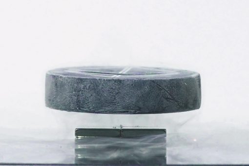
A resistance that falls to zero is necessary evidence for superconductivity, but on its own it is not sufficient – a short circuit does the same thing. The second, independent signature is the Meissner effect: the expulsion of magnetic field from the interior of the material, which is what makes a cooled superconductor levitate above a magnet. A convincing demonstration shows both, which is why a resistance measurement and a levitation experiment belong in the same lab session.
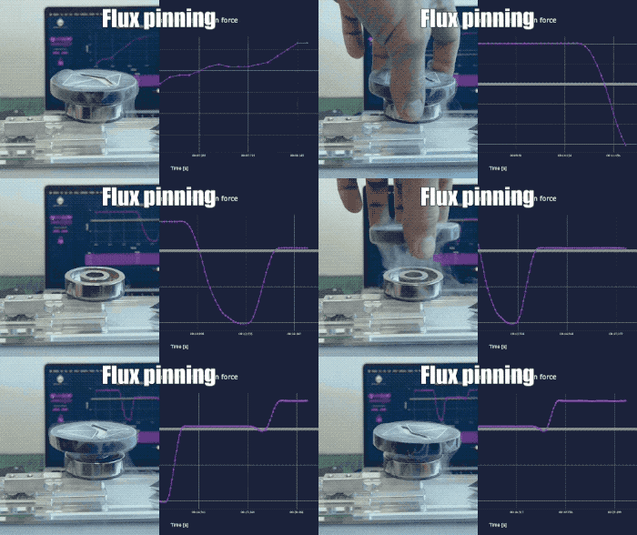
Related reading: room temperature superconductors and the flux-pinning force experiment.
Learn more and perform these experiments using our 4-point measurement kit and Superconductivity Experiment kit: